Image to Constellation Map for Wireless Communication
Images are edge-detected and downscaled, then transmitted over QAM modulation with a software-defined radio. For fun (no real practical application).
August 2025
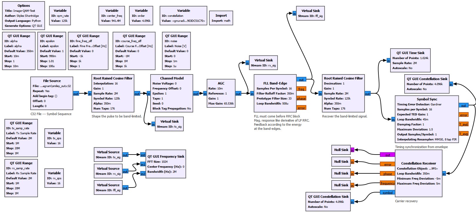
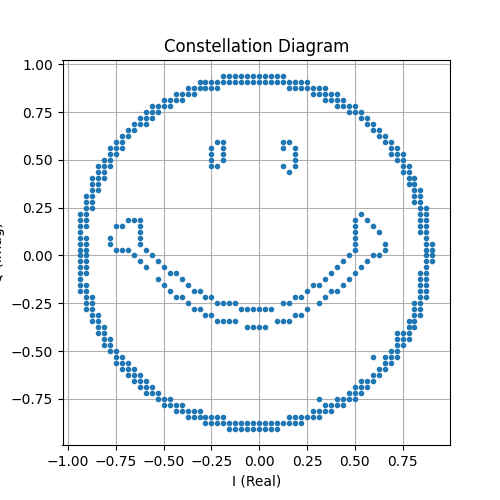
I always found the constellation diagram to be a handy way to measure and visualize the in-phase and quadrature parts of a signal, so I thought it would be fun to try to map an image directly on the constellation diagram. First, I had to process the image. I grayscaled the image, downsized it, convolved it with a Sobel, and finally applied a threshold that either puts the image values to 255 or 0. This was all fairly easy to implement with OpenCV. Nonetheless, it produced a 64x64 pixel image with well-defined edges suitable for conversion into a .c32 file.


In the real world, the constellation diagram would appear very noisy. It is ultimately limited by external factors in the environment as well as the resolution of the ADC and DAC in the software-defined radio. I had an 8-bit ADC and DAC, which is really only good for QPSK (4-QAM). Some sources online say that a higher order modulation of 64-QAM can be implemented practically. The best that I could do was simulate the channel.
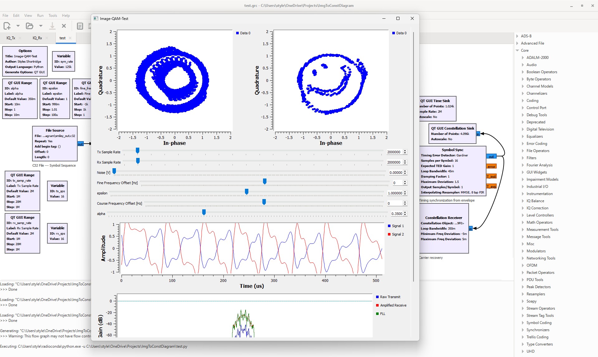
The FLL is unnecessary, but I had fun experimenting with how different frequency offsets imposed over the channel affects the reception of the signal with and without the FLL. I found that you can deviate ~80 KHz from the signal with the FLL. Pretty amazing!
Some tests in a real environment were also striking.
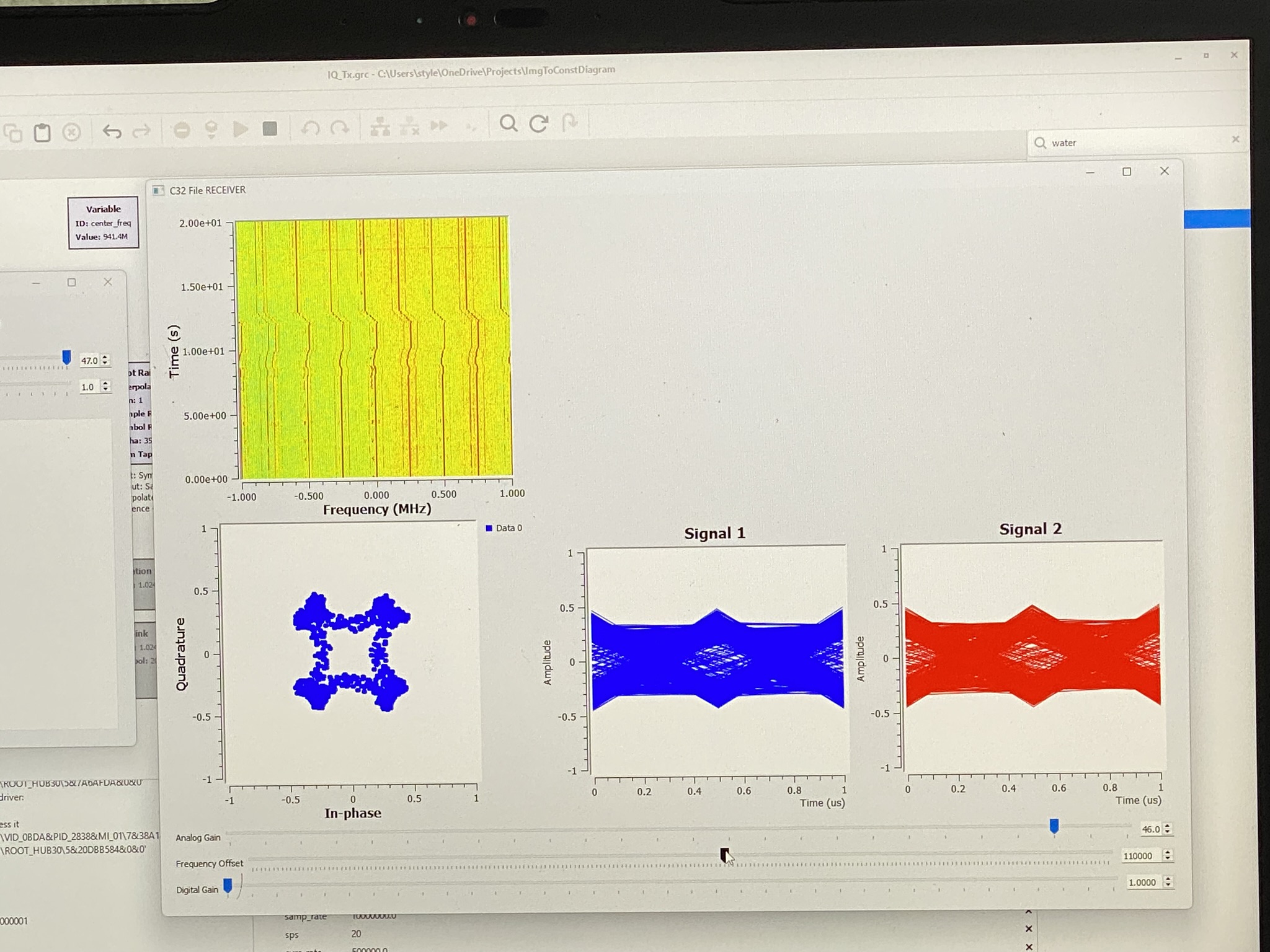
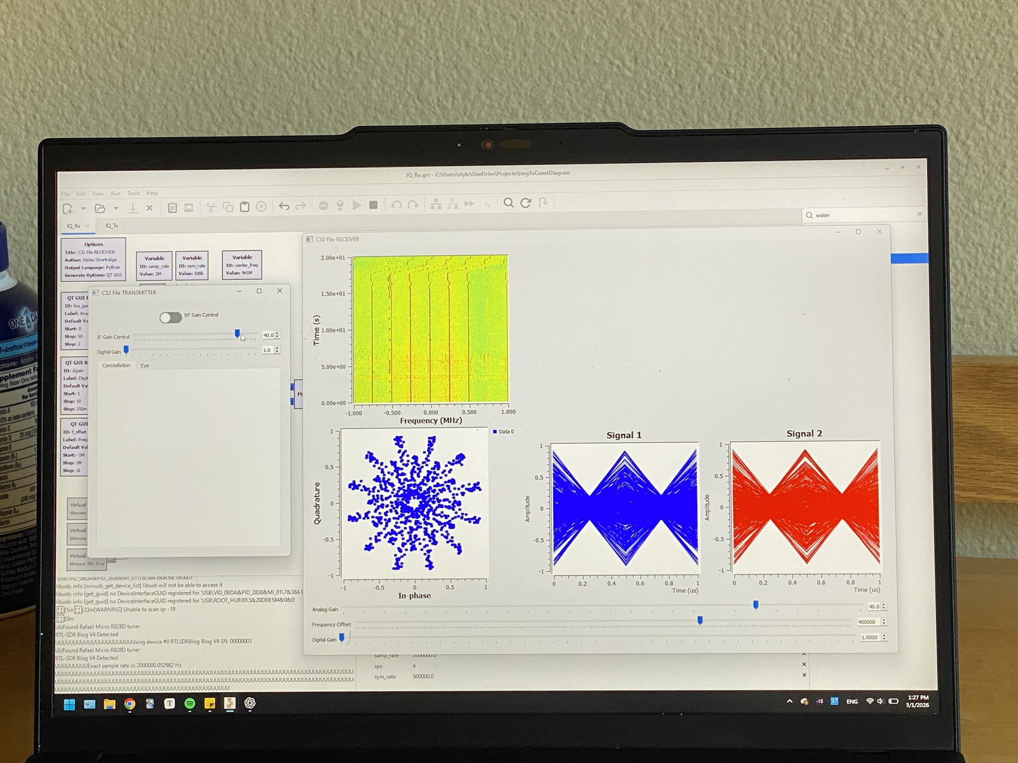
The spectrum shows a lot of harmonics in my original tests. Even if I was operating at low power, I was not being a good neighbor on the spectrum.